Best Info About What Is The Maximum Power Of IRF3205

Unlocking the Potential
1. Understanding Power Dissipation in MOSFETs
So, you're curious about the IRF3205 and how much power it can handle, huh? Well, you've come to the right place! Forget those dry, technical datasheets for a moment. Let's talk real-world performance. The IRF3205, at its heart, is a MOSFET (Metal-Oxide-Semiconductor Field-Effect Transistor). It's a workhorse in many electronic circuits, switching current on and off like a tiny, super-fast valve. But like any component, it has its limits. Pushing it too hard can lead to thermal runaway and a very unhappy MOSFET, potentially releasing the magic smoke that makes electronics work (or rather, not work!).
The key to understanding the maximum power of the IRF3205 lies in understanding power dissipation. Simply put, power dissipation is the amount of electrical power converted into heat within the device. This heat is generated due to the current flowing through the MOSFET and the inherent resistance within it. The higher the current and the higher the resistance, the more heat is produced. Think of it like rubbing your hands together really fast; the faster you rub and the harder you press, the more heat you generate. The MOSFET is doing the same thing, just on a microscopic scale.
Now, this heat needs to go somewhere. If it doesn't, the temperature of the MOSFET will rise, and rise, and rise... until it exceeds its maximum operating temperature. This is where things get interesting (and usually, expensive, if you're replacing fried components). The ability of the MOSFET to shed this heat depends on several factors, including the ambient temperature, the size and effectiveness of any heat sink attached to it, and the airflow around the device.
Therefore, there's no single, simple answer to the question of "maximum power." It's a balancing act between the electrical power being dissipated as heat and the ability of the MOSFET to get rid of that heat. This balancing act is what determines the practical, safe operating limits. Think of it like running a marathon. You can run faster if it's a cool day and you're well-hydrated, but you'll slow down considerably on a hot, humid day, even if you're the same runner.

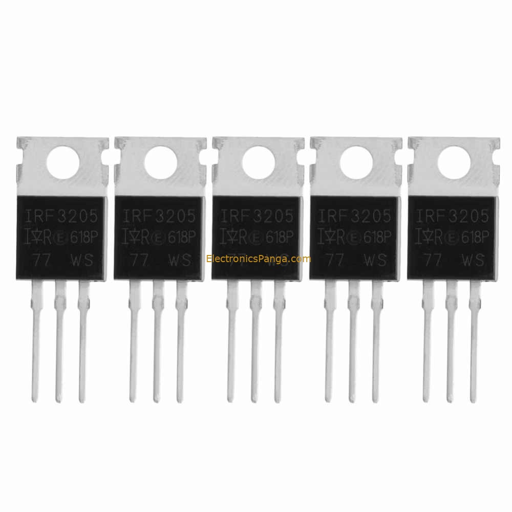
IRF3205 Power MOSFET Pinout, Application And Datasheet
Deciphering the Datasheet
2. Important Parameters to Consider
Alright, let's peek at that datasheet after all. But don't worry, we'll keep it simple. The datasheet is your friend, but it speaks a slightly different language. Two key parameters determine the power handling capabilities: the maximum drain current (Id) and the drain-source on-resistance (Rds(on)). The maximum drain current is the highest current the MOSFET can theoretically handle without being damaged. The Rds(on) is the resistance when the MOSFET is fully turned on; lower is better, as it means less power is dissipated as heat. These two factors work together to determine how much heat the MOSFET will generate.
Now, here's where it gets a little tricky. The datasheet usually provides these values under ideal conditions — typically a case temperature of 25C (77F). In the real world, however, you're unlikely to be operating at such a low temperature. As the temperature rises, the Rds(on) also increases, leading to more heat generation. This is why it's crucial to consider the "derating" curves provided in the datasheet. These curves show how the maximum drain current and power dissipation decrease as the temperature increases.
Furthermore, consider the pulsed drain current (Idm). This specification indicates the maximum current the device can handle for a short period. It's usually significantly higher than the continuous drain current. This parameter is vital for applications involving PWM (Pulse Width Modulation) or surge currents. However, remember that exceeding the continuous current rating for extended periods, even if the pulsed current is within spec, will eventually lead to failure. Think of it like sprinting. You can sprint faster than you can run a marathon, but you can't sprint forever.
So, the datasheet gives you the theoretical limits, but practical application demands careful consideration of operating conditions and thermal management. Treat the datasheet values as guidelines, not absolutes. The art of electronics is understanding how to apply those guidelines to your specific project, keeping in mind the real-world constraints.

IRF3205 Power Transistor Field Effector IRF3205PBF TO220 MOSFET Tube
The Role of Heat Sinks and Thermal Management
3. Keeping Things Cool
Okay, we've established that MOSFETs generate heat. Now, how do we deal with it? That's where heat sinks come in. A heat sink is essentially a metal device designed to conduct heat away from the MOSFET and dissipate it into the surrounding air. They come in various shapes and sizes, and their effectiveness depends on their surface area, material, and airflow.
Choosing the right heat sink is crucial for ensuring the long-term reliability of your IRF3205. A too-small heat sink will allow the MOSFET to overheat, while an overly large heat sink may be unnecessary and add unnecessary bulk and cost to your project. The key is to find a balance. Calculating the required heat sink size involves some thermal calculations, taking into account the power dissipation, the ambient temperature, and the thermal resistance of the heat sink and the thermal interface material (TIM) between the MOSFET and the heat sink.
Speaking of TIM, don't underestimate its importance. TIM, such as thermal paste or thermal pads, fills the microscopic gaps between the MOSFET and the heat sink, improving the thermal contact and allowing heat to flow more efficiently. Applying the correct amount of TIM is also important; too much can actually hinder heat transfer. A thin, even layer is usually best.
But it's not just about the heat sink and TIM. Airflow also plays a significant role. Forced air cooling, using a fan, can significantly improve the heat dissipation capabilities of the heat sink. This is particularly important in enclosed environments where natural convection is limited. Consider the overall enclosure design and ensure adequate ventilation to prevent heat buildup.

Real-World Examples and Calculations
4. Putting Theory into Practice
Let's get a little more concrete. Suppose you're using the IRF3205 in a motor control circuit, and you estimate that it will be dissipating 10 watts of power under normal operating conditions. You're operating in an ambient temperature of 30C (86F). What heat sink do you need?
This is where those thermal calculations come in. You'll need to determine the thermal resistance required of the heat sink. This involves subtracting the ambient temperature from the maximum allowable junction temperature (typically 175C for the IRF3205) and dividing by the power dissipation. This will give you the maximum allowable thermal resistance from the junction to the ambient air. Then, you'll need to subtract the thermal resistance of the MOSFET's case and the TIM to determine the required thermal resistance of the heat sink itself.
This might sound complicated, but there are plenty of online calculators and resources available to help you with these calculations. A good starting point is to consult the datasheet of the heat sink manufacturer. They typically provide information on the thermal resistance of their heat sinks under various conditions.
Remember that these calculations are just estimates. It's always a good idea to test your circuit under real-world conditions and monitor the temperature of the MOSFET to ensure it's not overheating. A simple infrared thermometer can be a valuable tool for this purpose. If the MOSFET is running too hot, you may need to increase the size of the heat sink or improve the airflow.

IRF3205 Power Transistor Field Effector IRF3205PBF TO220 MOSFET Tube
Practical Limits and Safety Considerations
5. Avoiding the Magic Smoke
Ultimately, the maximum power you can safely draw from an IRF3205 is constrained by how efficiently you can remove the heat it generates. While the datasheet might suggest impressive peak values, relying on those numbers without proper thermal management is a recipe for disaster. It's always wise to err on the side of caution.
Overheating is not the only concern. Exceeding the voltage or current ratings, even for a brief period, can also damage the MOSFET. Transient voltage spikes, for example, can easily exceed the maximum drain-source voltage rating and cause immediate failure. Protection circuits, such as transient voltage suppressors (TVS diodes), can help to protect the MOSFET from these spikes.
Another important consideration is electrostatic discharge (ESD). MOSFETs are particularly sensitive to ESD, and even a small static charge can damage the device. When handling MOSFETs, always use proper ESD precautions, such as wearing an ESD wrist strap and working on an ESD-safe surface. This will help to prevent accidental damage and ensure the long-term reliability of your circuits.
Finally, remember that electronic components are not infallible. Even with proper design and precautions, components can still fail. It's always a good idea to include redundancy or fail-safe mechanisms in your circuits to prevent catastrophic failures. This could involve using multiple MOSFETs in parallel to distribute the current load or incorporating over-current protection devices to shut down the circuit in the event of a fault. The goal is to design a robust and reliable system that can tolerate occasional component failures without causing significant damage or safety hazards.

FAQ
6. Your Burning Questions Answered
Still have questions? No problem! Here are a few frequently asked questions about the IRF3205 and its power handling capabilities.
Q: What's the maximum power I can really get out of an IRF3205?
A: It depends! Seriously. It depends on your cooling setup. With a good heat sink and decent airflow, you might be able to push it to 50-75 watts. Without a heat sink, you're looking at a few watts, tops. Test, measure, and be safe!
Q: Can I use multiple IRF3205s in parallel to increase the power handling?
A: Absolutely! This is a common technique for increasing the current capacity of a circuit. However, you'll need to ensure that the current is evenly distributed among the MOSFETs, typically by using small balancing resistors in series with each gate.
Q: What happens if I exceed the maximum power rating?
A: Bad things! The MOSFET will overheat, and eventually, it will fail. This could involve a spectacular display of sparks and smoke, or it could be a more subtle failure that's difficult to diagnose. Either way, it's best to avoid this scenario by proper design and testing. Remember the magic smoke? Once it's gone, it's gone!
Q: Where can I find the best heat sink for my IRF3205?
A: Online electronics retailers are your friend! Look for heat sinks designed for TO-220 packages (which is the package the IRF3205 comes in) and pay attention to the thermal resistance rating. The lower the thermal resistance, the better the heat sink.